Clipper multisim biased How to work positive clipper circuit in real time. Positive clipper biased circuit
Active Clipper Circuit (Clipper Circuit using op-amp) Explained - YouTube
Positive negative clipping clipper waveforms waveform circuit output diode biased clippers circuits combination
Clipper diode output input resistor connected consists circuits using
Waveform clipping: positive & negative clipping circuit designClipper diagram clipping waveform Clipper clamper difference between circuit diode voltage electronics positive using ac load half electronicscoachClipper positive negative clamper circuits clippers circuit electronics diode voltage biased double figure read.
Waveform clipping: positive & negative clipping circuit designClipper positive circuit Diode clippers – an overview of clipping circuitsMultisim clipper.

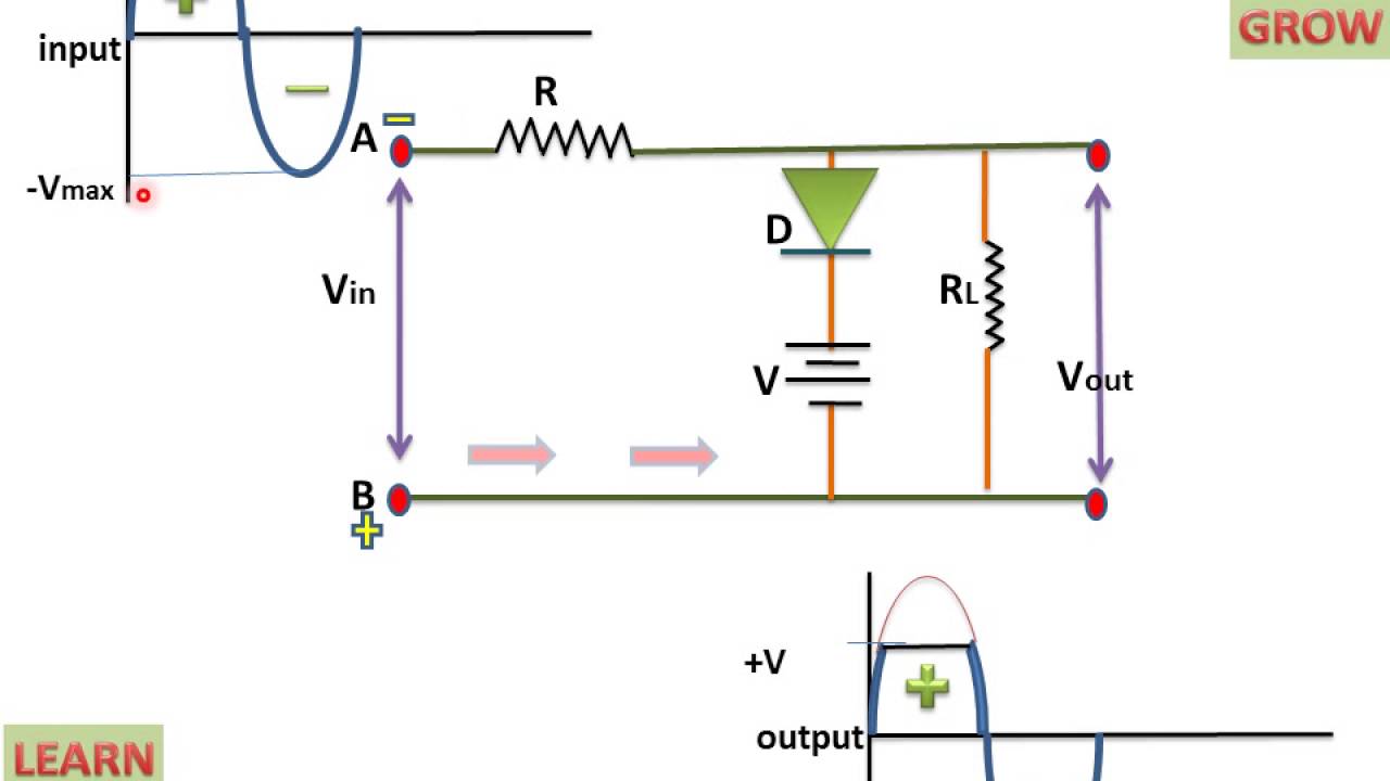
Positive biased clipper circuit
What is a clipper circuitWhat are clipper circuits? definition, classification and applications Biased positive clipper circuitPositive series biased clipper circuit 2.
Positive shunt clipper circuit diagramWhat are clipper circuits? definition, classification and applications What are clipper circuits? definition, classification and applicationsPositive clipper.

Biased negative clipper circuit
Circuits diode clipping clipper clippers biased combination waveforms circuitstodayClipper & clamper Clipper negative circuit biased acDiode clippers – an overview of clipping circuits.
Active clipper circuit (clipper circuit using op-amp) explainedDiode clippers – an overview of clipping circuits Clipper circuit circuits positively biased negativeCircuit clipping waveform positive clamper negative diagram clipper buffer frequency clamping fig modulated diy engineersgarage output.

Clipper circuits using diode
Clipper positive series circuit circuits diagram diode output waveform definition input electronics thus named soClipper circuits Clipper circuitsClipper positive biased circuit.
Difference between clipper and clamper (with comparison chartClipping circuit positive diagram waveform fig diy Clipper diode circuitdigest circuitsClipper positive circuit circuitlab description.

Clipper positive series circuits clipping negative parallel biased figure
Clipper biased negative clipping circuit diode clippers positive diagram waveform circuits voltage signalPositive clipper circuit Diode clipper circuits: design & demonstrationDiode clipper.
Clipper series circuits positive circuit clippers rectifier half negative shunt input types acMultisim circuit clipper positive diagram shunt Clipper positive diode negative circuit shunt clipping circuits series voltage clippers input biased half combination givenPositive series clipper circuit.