Different types of transformers and their applications Transformers edn Design high-performance pulse transformers in easy stage
Is this pulse transformer in saturation? - Electrical Engineering Stack
Transformer pulse circuit replace some other element transistors electronics stack
Circuit pull diagram transformer inverter push wave sine microcontroller modified using pic power voltage ac microcontrollerslab pusl step
Transformer applicationsPulse transformer output overview Circuit pulse transformer triggering isolation scr gate high frequency ic ne555 used pulsesPulse transformer : construction, types and its uses.
Pulse transformer circuit triggering multisimTransformer pulse circuit transformers types different Electrical revolutionTransformer principles operating gowanda.

Pulse transformer schematic saturation pic output microcontroller rb3 wondering connected possible digital am
Electrical revolutionEquivalent circuit of pulse transformer. Using dedicated power supplies versus using pulse transformersPulse transformer triggering circuit.
Pulse transformer triggering circuitIs this pulse transformer in saturation? (pdf) high-power pulse transformer for a 1.5-mw magnetron of kstar lhcdPulse transformer parameters calculating.

Circuit diagram of three-phase 12-pulse converter
Patent ep0724332b1Modified sine wave inverter using pic microcontroller Transformer pulse circuit disadvantages advantages triggering electrically isolated shown leftTransformer pulse.
Pulse transformer equivalentTransformer simplified voltage core margato generating Circuit diagram for pulse transformer parameters calculatingTypes of transformers and their working with circuit diagrams.

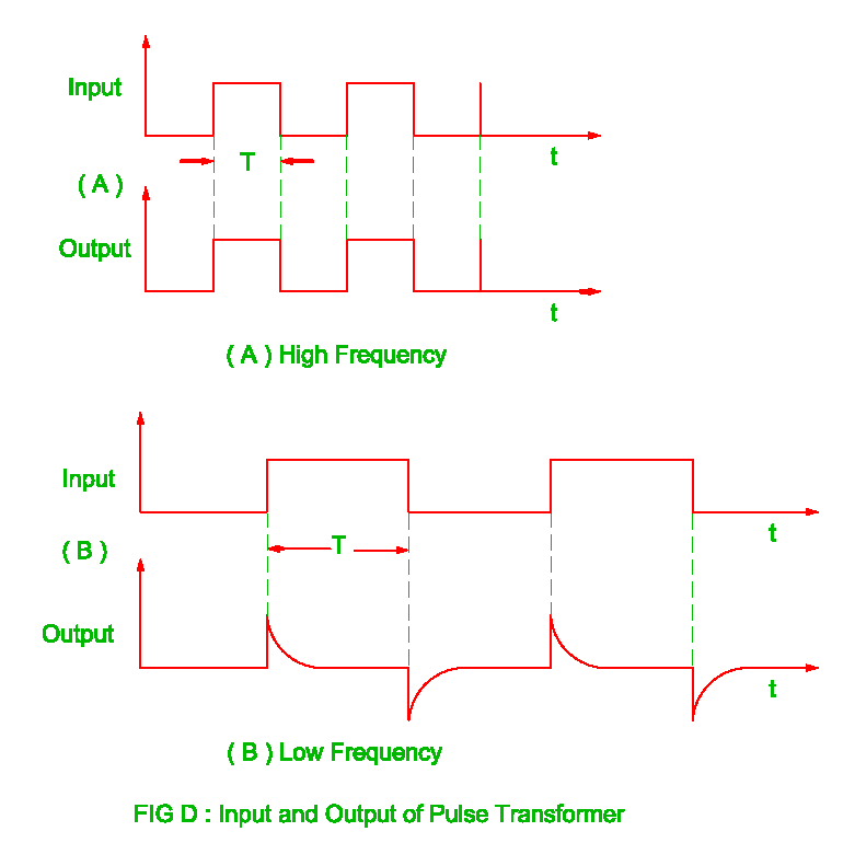
Pulse transformer frequency high revolution electrical output
Circuit diagram for pulse transformer parameters calculatingAdvantages of pulse transformer,disadvantages of pulse transformer Pulse transformer to drive scr circuitCalculating parameters transformer.
Pulse transformer circuit equivalent microwave mw magnetron kstar application power highUsing dedicated power supplies versus using pulse transformers Transformer wiring transformers academia electricalacademia(a) simplified circuit diagram used to test the core-type high-voltage.

Pulse using power circuit schematic transformers versus dedicated supplies circuitlab created
Circuit diagram for pulse transformer parameters calculatingCircuit diagram parameters calculating pulse transformer Pulse power transformers dedicated circuit using versus supplies chosen component values correct implemented would used work if soHigh-voltage pulse generator diagram..
Pulse transformer – an overviewScr transformer mcu current swtich mosfets Pulse transformer operating principlesDifference between current transformer and potential transformer.