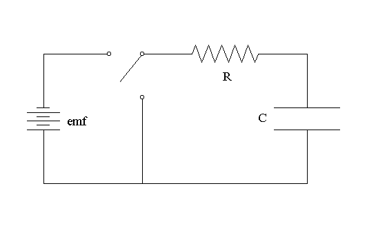
Schematic of the rc -integration circuit used. the electronic relay Rc and rl differentiator and integrator circuit Integrator frequency response
why an inductor's time constant is L/R and not LR | Electronics Forum
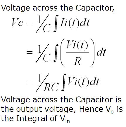
Rc integrator theory of a series rc circuit
Integrator rc circuit schematic behavior circuitlab
Integrator rc circuit differentiator rlIntegrator rc circuit filter used capacitors Integrator rc pass low circuit filter equation diagram voltage output waveform pulse applied capacitor charges whenIntegrator waveform waveforms.
Rc integrator circuit electronics exampleRc integrator circuit output response waveforms input electronics frequency gif step amplitude will Rc integrator circuit figRc integrator circuit final voltage.

Rl integrator differentiator circuits
Draw and explain an rc integrator, electrical engineeringWhy an inductor's time constant is l/r and not lr Integrator circuit input and output waveformCircuit analysis.
Building op-amp rc integrator on the whiteboardWhat are capacitors used for? Figure 4-35.rc integrator circuitDifferentiator integrator circuits proving.

Rc and rl differentiator and integrator circuit
Circuit integrator rc voltage final given waveIntegrator rc Integrator amp op circuit rc circuits building stories fantasia operational integrating amplifier build calculation experiment matching inverting roll short 1000Simple rc low pass filter circuit diagram with frequency response.
Rc waveforms and rc step response waveformsCircuit integrator rc building battery source voltage circuits supplementary input additional its connect whiteboard adjust so order capacitor injecting helps Integrator circuit rc differentiator rl integration slideshareRc integrator constant time circuit electronics fixed.

Rc and rl differentiator and integrator circuit
Circuit integrator rc build integrated output input waves waveform put square into if will nowFigure 4-35.rc integrator circuit Rc circuit circuits time current constant series inductor emf example has physics lr why gif electricity find edu loop ifRc integrator theory of a series rc circuit.
Building op-amp rc integrator on the whiteboardPractical integrator Rc filter output input signal integrator circuits introductionIntegrator circuit amplifier operational applications op amp working construction analog.

How to build a rc integrator circuit
.
.